Ballast wagon: the tooling process
The “tooling process” for the moulds associated with a ready-to-run railway model is a term many modellers are familiar with, but an explanation and accompanying photographs are not always provided by manufacturers. Here, we’re going to show you what’s involved, using the tooling for Irish Railway Models’ forthcoming ballast wagon as the basis.
The tools that make up each mould interlock much like a 3D jigsaw.
The tools are shaped from blocks of steel through a process called electrical discharge machining – also known as spark erosion. Every single cut, groove and rivet on the chassis is individually shaped by a copper electrode (examples can be seen in the upper part of the image below). The steel in the centre will become the female part of the chassis mould. The NEM pockets at either end can clearly be seen.
The steel is submerged in a dielectric fluid and then a robotic arm takes each electrode one by one, presses it against the steel and an electrical charge passes through it. This process leaves behind a perfect impression of the imprint on the electrode, which is expended as a result. The process must be repeated over and over again to form each component.
In the photo below, the die on the right has two channels cut into it. These are ‘gates’ which allow the molten plastic to runs into the mould when it is assembled.
The mould is then assembled by putting the components together and placing them in a rig as shown below. The holes on the sides and ends of the shape in the centre represent where the inside of the ballast hopper is, and the metal dies are built up from there. Plastic is then injected.
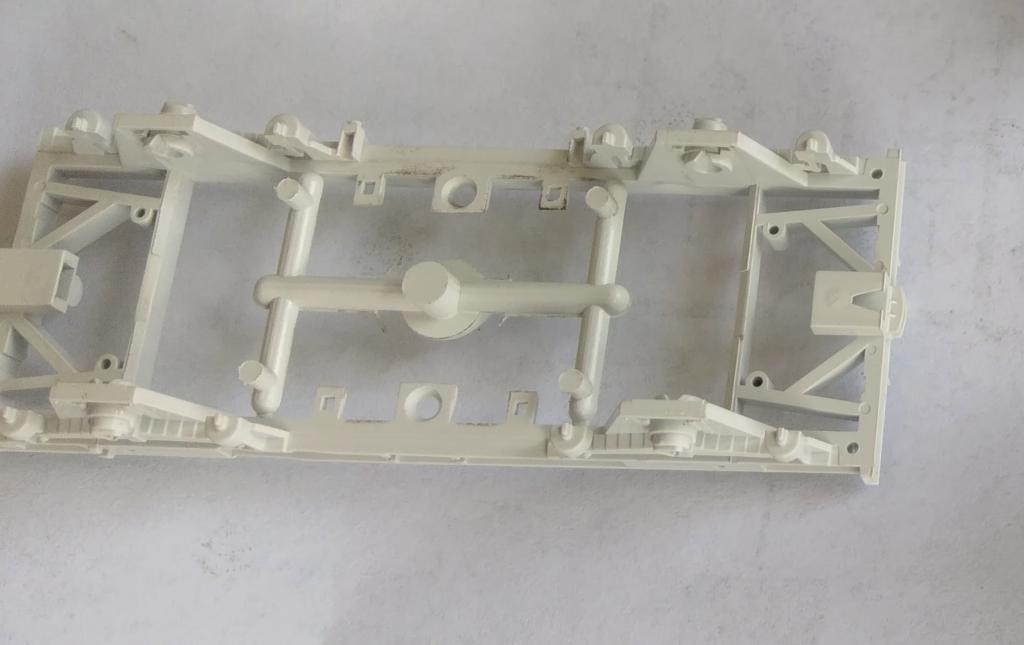
Here’s how the ballast wagon chassis looks when first removed from the mould, complete with sprues which will have to be removed by hand:
And here is some of the detail tooling:
The individual parts are then assembled by hand on a production line before paint and tampo printing is applied. The model is then ready to be packaged and shipped.


